§ 2.3 - Single Positive Power Supply, Unregulated
Back to → Main Power Block PageBefore you attempt this build, please:
- Read through the numbered build procedure with the idea of performing the listed steps in order
- Examine the PCB layout
- Examine the schematic diagram
- Refer to each of the linked pages in the "See also" list
This will help ensure that you will have the best possible experience, resulting in a build that works the way you expect it to.
Schottky diodes are recommended; these diodes have a much lower forward voltage drop, and so will waste less power and run cooler under load.
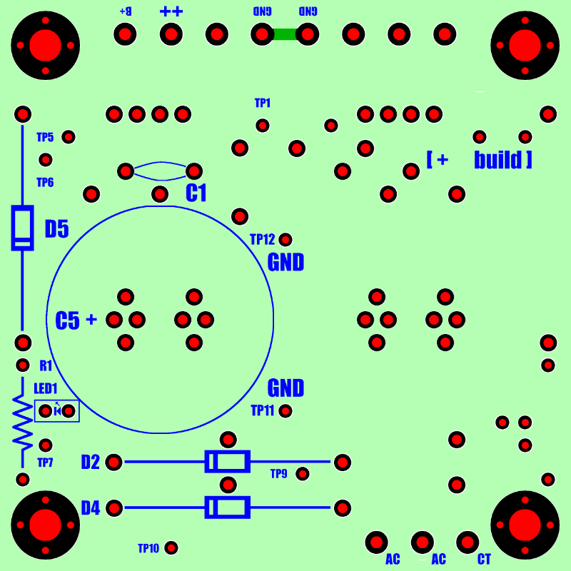
- Optional: Install test points — Important: If these are used, they must be first components installed!
- D2 — at least a PIV equal to the total secondary voltage of T1, 2 amps or more. Observe polarity.
- D4 — at least a PIV equal to the total secondary voltage of T1, 2 amps or more. Observe polarity.
- D5 — steering diode — at least a PIV equal to the total secondary voltage of T1, 2 amps or more. Observe polarity.
- R1 — calculate the ohms and watts values for R1 here.
- C1 — ceramic .22 uF — equal to or higher than the total secondary voltage voltage of T1
- C5 — Polarized electrolytic — Calculate the uF and WV value of C5 here. Observe polarity.
- LED1 — a low-power LED of whatever color you prefer. Observe polarity.
- T1 — Center-tapped-winding secondary power transformer (see Choosing a Transformer)
| See also: | Choosing a Transformer Calculators Recommended Tools Mounting to Wood Surfaces Power Block Parts Sources Wiring to Terminal Blocks |
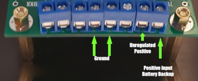
Warning: If battery backup is used, the battery backup input voltage must be less than the minimum ripple voltage plus the steering diode drop (.65 volts for Si diodes, .25 volts for Schottky diodes) of the loaded power supply. You can use the filter capacitor calculator to ensure that the minimum ripple voltage is above the battery input voltage minus the steering diode drop. If the battery voltage minus the steering diode drop is above the minimum ripple voltage, the battery will discharge continuously until it falls below this level, which will usually mean the battery can no longer function as a backup power source.
Note: If you plan to build into a wood enclosure or onto a wood surface, see Mounting to Wood Surfaces before building.
Tip: The footprints for filter capacitors C5 and C6 are designed to accommodate many different capacitor sizes and lead spacings. Each of the four-hole "diamonds" is one connection; you can use any one of the four diamond through-holes to connect one lead of your capacitor(s.)
Carefully observe polarity as shown in the layout diagram below and connect each lead of your filter capacitors into the correct diamond.

Carefully observe polarity as shown in the layout diagram below and connect each lead of your filter capacitors into the correct diamond.

Have a question? Ask us via email
Website Keyboard Navigation
, Previous Page . Next Page
o Ordering g Glossary s Sitemap u Updates
, Previous Page . Next Page
o Ordering g Glossary s Sitemap u Updates
![]()