§ 8 - Calculators
Back to → Main Power Block PageBack to → Main Mixer Block Page
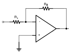
§ 8.1 - Amplifier Feedback Resistance Calculator
This is a calculator you can use to determine the value of the feedback resistor for the Mixer Block to achieve a specific gain when the input resistance is known. For a line-level mixer, the input resistance should be 10 k-ohms, or 10000 ohms, and the voltage gain ratio 1, or 0 dB:
| Ri (input impedance), ohms: | ||
| Desired voltage gain in dB: | ||
| Desired voltage gain ratio: | ||
 | ||
| Rf value: ----- ohms | ||
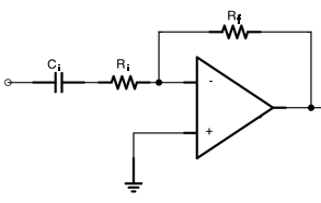
§ 8.2 - AC Amplifier Component Calculator
Given the mixer or amplifier configuration's feedback resistor (Rf), input resistor (Ri), and input coupling capacitor (Ci), this calculator graphs the resulting gain across audio frequencies:
| Ci, uF: | ||
| Ri, ohms: | (Line level impedance is ~10 k-ohms) | |
| Rf, ohms: | ||
 | ||
|
||||
§ 8.3 - Power Supply LED Current Limit Resistor Calculator
This is a calculator you can use to determine the minimum value of the current limiting resistors for the Power Block's LED power indicators.
You almost certainly don't need the LED to be the very brightest it can be; consider specifying 1/2 or 1/4 of the LED's maximum current rating in the calculator below, and you'll have a decent amount of light, and a much longer operating lifetime for the LED.
Enter all the values into the provided fields. Then press the Calculate button to obtain the result.
Use the a resistor value that is equal to, or greater than, the calculated ohms value (and keep the tip above in mind!)
| T1 secondary leg RMS voltage, volts: | Peak secondary leg volts: ------ VAC | |
| Rectifier diode voltage drop, volts: | .25 for Schottky diodes, .65 for PN Silicon diodes | |
| LED operating current, ma: | ||
| LED forward voltage, volts: | Resistor voltage drop: ------ VAC | |
| Result: | ---- ohms, --- watt |
§ 8.4 - Power Supply Filter Capacitor Calculator
This is a calculator you can use to determine the value of the Power Block's filter capacitors, C5 and C6, as well as to predict the power dissipation of the voltage regulator ICs.
Once you've determined the calculated uF value, the next standard uF value that is larger than the value given is shown to the right; this is the uF value to use in your design.
The default values below are set up for:
- The US AC line frequency (60 Hz)
- Silicon (PN semiconductor junction) rectifier diodes with a forward voltage drop of .65
- Electrolytic capacitor part tolerance of 10%
- A transformer with 12 VAC output for each of the two legs of its secondary (this requires a 24 VAC, center-tapped transformer)
- A maximum of 1 ampere of current output
- A ripple voltage floor of 15 VDC, which is .5 volts above the 7812 and 7912 voltage regulator's minimum input voltages
- A regulator output voltage of 12 volts
With these default values, the calculated specifications with the minimum usable values are 3477 uF with a WV of 22.7 volts.
However: The closest standard part that will work is 3500 uF at 25 WV, so that's what would ideally be used in that case.
The calculator indicates that the peak power dissipation for the example is 4.32 watts, which means substantial heat sinks would be required, as these TO-220 case regulators can only dissipate about half a watt without a heat sink.
Electrolytic capacitors can be a little tricky: Try to keep within one to two times the calculated values. Otherwise, too high a uF value, and you'll stress the transformer and the rectifier diodes... too high a WV, and the capacitor may not reach its specified uF rating.
If you're building a regulated Power Block, then you need to consider the indicated regulator peak power dissipation.
The regulator's power dissipation depends on the load current of the regulator and the input voltage to the regulator, which varies (which is why peak, average and minimum power dissipation values are provided below.) However, you should always assume the peak power is the actual dissipation; that's the worst case. If you know the regulator will only have 100 ma drawn from it, then you can enter that in the calculator and heat sink (or not) accordingly.
In all cases, you must enter the maximum current that the power supply will be called upon to deliver to its load(s.)
If peak power dissipation for a TO-220 case regulator (78xx, 79xx) is above about half a watt at room temperature (about 75°F or 23.3°C), then you will need a heat sink. At temperatures above room temperature (for instance, inside a closed cabinet, or if the regulator is sitting in the sun, or operating in a hot vehicle), you'll need a heat sink for less wattage, as the amount of heat the regulator can dissipate drops as the ambient temperature goes up. You can never go wrong by adding a heat sink even if you don't think you need one.
Also, if you use a capacitor larger than that recommended by this calculator, you will move the average power dissipation of the regulator towards the peak power dissipation, as the average input voltage to the regulator will be higher.
You can press Calculate when the page first loads, or immediately after a page re-load, to see the calculator work out the answer for the default values.
Enter the six (or seven, if you're building a regulated Power Block) values for your design, then press the Calculate button below:
| AC line frequency, Hz: | ...typically 50, 60, or (rarely) 400 | |
| Rectifier diode voltage drop, volts: | .25 for Schottky diodes, .65 for PN Silicon diodes | |
| Capacitor tolerance, percentage: | Typically 10% to 20% | |
| T1 secondary leg RMS voltage, volts: | Peak secondary leg volts: ------ VAC after diode drop | |
| Maximum output current, amperes: | 78xx and 79xx series regulators are usually capable of 1 amp | |
| Ripple voltage floor, volts: | at least .5 volts above the regulator's minimum input voltage | |
| Regulator voltage, volts: | (ignore for unregulated Power Block builds) | |
| ---- uF, -- WV | Closest standard part: -- uF, -- WV | |
| Regulator peak power dissipation: | -- watts (ignore for unregulated Power Block builds) | |
| Regulator average power dissipation: | -- watts (ignore for unregulated Power Block builds) | |
| Regulator minimum power dissipation: | -- watts (ignore for unregulated Power Block builds) | |
For instance, with the above default values, the value you end up with after pressing Calculate is 3477 uF, so the next standard value is 3500 uF, but perhaps you've only got some 4000 uF caps in your parts bin. Those will be okay.
But if you significantly increase the value, say to around 5 times the called-for value (20,000 uF), now you've created a situation where when the power supply is first turned on, there is a five-times-normal current inrush to the filter capacitors. That current has to go through the rectifier diodes, heating and stressing them considerably more than is actually called for.
There's a practical limit to this, and that is created by the internal impedance of the transformer's secondary windings. At some point, there's just no more current that can be provided by the transformer. However, if the internal impedance of the secondary is all that's limiting the current out of the transformer, that's not good for the transformer, either.
So go gently into that good parts bin, lest you find yourself raging against the dying of your diode(s.)
Have a question? Ask us via email
, Previous Page . Next Page
o Ordering g Glossary s Sitemap u Updates