§ 3.3 - DC-coupled Single-channel Stereo Amplifier
Back to → Main Mixer Block PageBefore you attempt this build, please:
- Read through the numbered build procedure with the idea of performing the listed steps in order
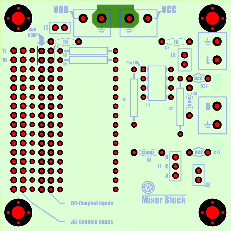
- Examine the PCB layout
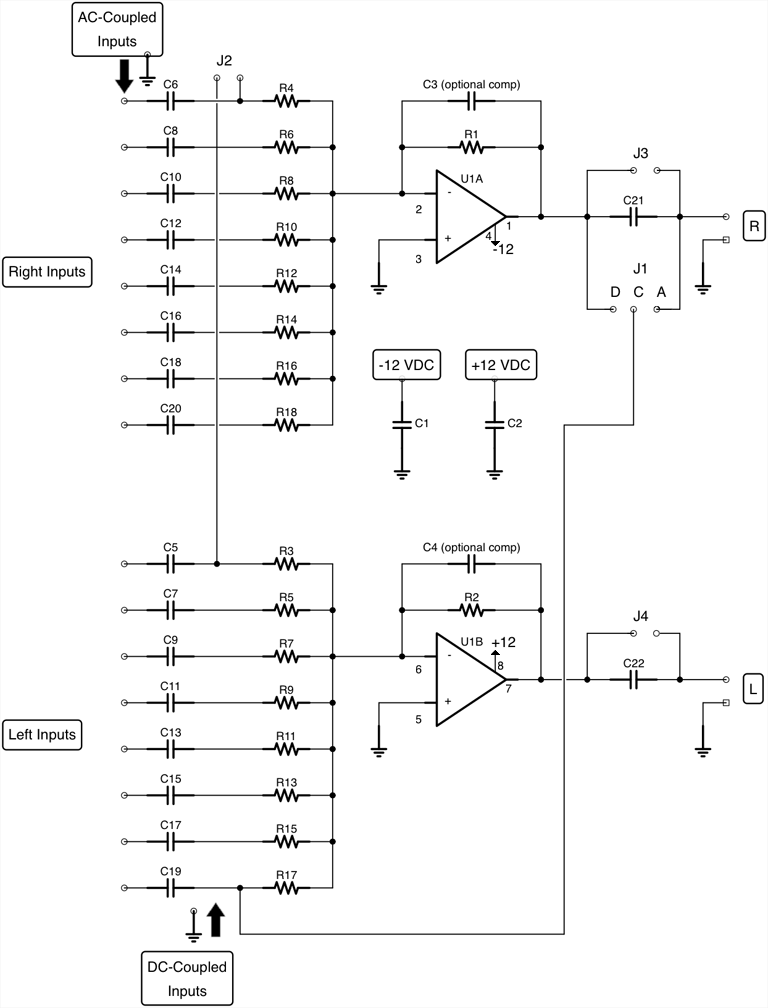
- Examine the schematic diagram
- Refer to each of the linked pages in the "See also" list
This will help ensure that you will have the best possible experience, resulting in a build that works the way you expect it to.
This Mixer Block build is a DC-coupled, unity- or higher-gain, single-channel, stereo, amplifier.
It has two signal inputs, and two amplified outputs of those signals, one on the L output, and one on the R output.
Input impedance of this buffer/amplifier build is 10 k-ohms.
Tip: To power this build of the Mixer Block with the Power Block, use the +/- 12 regulated Power Block build. If this is all you'll be powering, you won't need heat sinks on the Power Block, as the power requirements for the Mixer Block are very low.
Build Steps:
- C1—C2: .1 uF ceramic capacitor
-
C3—C4 optional: ceramic capacitors, only needed for op-amps that require compensation
TLO-72 and TLO-82 op-amps do not require compensation. Refer to the specific op-amp's datasheet for design values - C21—C22: 10 uF ceramic or other non-polarized capacitor
- Choose Unity Gain Buffer or Gain Amplifier build, then:
- R3—R4: 10 k-ohms 1/8th watt resistors
- U1: TLO-72 low-noise op-amp, can substitute TLO-82, or similar. Observe polarity. An IC socket is strongly recommended.
- Install 3-pin jumper J1 — use .100 inch (2.54mm) header pins; do not close
- Install 2-pin jumper J2 — use .100 inch (2.54mm) header pins; do not close
- Install 2-pin jumper J3 — use .100 inch (2.54mm) header pins; close with a header jumper cap
- Install 2-pin jumper J4 — use .100 inch (2.54mm) header pins; close with a header jumper cap
- If you will be using a 4-pin input connector, mount it now at the dark blue box near C1; otherwise, connect the input and signal ground wires now
- Install connectors, quantity 4, optional: 5.08mm (.200in) Spacing, 2-pin PCB Mount Screw Terminal Blocks. Or you can just wire the output from the indicated connections.
- Lastly, install M3 mounting hardware at all 4 mount points
Tip: If you would like to AC-couple the outputs while retaining the DC input coupling, remove the jumper caps from J3 and J4.
| See also: | Recommended Tools Mounting to Wood Surfaces Mixer Block Parts Sources Wiring to Terminal Blocks |
Have a question? Ask us via email
Website Keyboard Navigation
, Previous Page . Next Page
o Ordering g Glossary s Sitemap u Updates
, Previous Page . Next Page
o Ordering g Glossary s Sitemap u Updates
![]()