§ 2.17 - Off Board Regulator Mounting
Back to → Main Power Block Page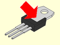
- For a positive & positive build, both regulator tabs are ground. This is the only build type where not insulating the regulators is safe when they are mounted to the same heat sink.
- For a negative & negative build, both regulator tabs are unregulated input voltage from different unregulated sources and should be insulated from each other if they are on the same heat sink. If insulation is not used, the heat sink will carry the unregulated input voltage and the unregulated supplies will be joined, both of which are probably undesirable.
- For a positive & negative build, the regulator tabs are different, one is the negative supply voltage and the other is ground, and so they must be insulated from each other if they are on the same heat sink.
In cases where output power demands upon Power Block voltage regulators exceed the regulator's ability to dissipate the heat generated with an on-regulator heat sink (above about 1.5 watts), off-board heat sinks are called for.
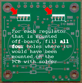
The Power Block is supplied with two reversible off-board regulator mounting PCBs. Each of these boards is designed to work with either 78xx or 79xx regulators; all you have to do is turn the PCB over and match the silkscreened text to the regulator type you are using, then mount the parts from (on) that side, which is called the component side.
This is very easily accomplished; instead of mounting the regulator on the Power Block PCB, for each regulator IC, in the following order, you:
Assembly
- Orient the remote regulator mounting board so the side matching your regulator type is the component side
- On the component side, install filter capacitors C1 (.22 uF) and C2 (.1 uF)
- Choose your preferred side and mount the In and Out connectors, if you're going to use connectors
- On the component side, solder the regulator to the remote regulator mounting board
- Apply heat sink compound to the back of the regulator IC
-
If needed (see above warning):
- Place an insulator on the heat sink compound you've applied to the regulator
- Apply heat sink compound to the other side of the insulator
- Mount the regulator IC (and insulator, if used) on the external heat sink
Wiring
- Connect a wire from a GND ground terminal of the Power Block PCB to a Gnd terminal of the remote regulator mounting board
- Connect a wire from the matching unregulated supply terminal of the Power Block PCB to the In terminal of the remote regulator mounting board
- Connect a wire from the remote regulator mounting board's Gnd terminal or pad to your load's ground
- Connect a wire from the remote regulator mounting board's Out terminal or pad to your load's power input
| Connection nomenclature is correct on both sides | ||
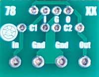
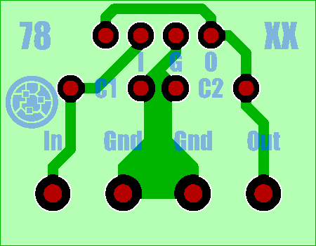
For reference, if the regulator is a 78xx series, then with the component side up and the connections facing you, the unregulated voltage In is on the left, and the regulated Out is on the right, with the two Gnd connections in the center.
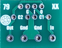
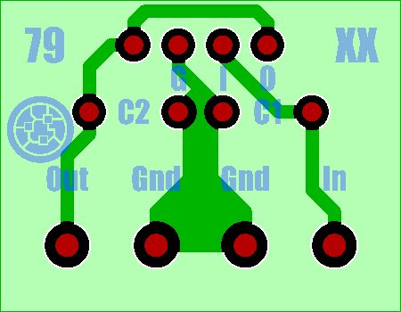
If the regulator is a 79xx series, then with the component side up and the connections facing you, the unregulated voltage In is on the right, and the regulated Out is on the left, with the two Gnd connections in the center.
| Off-board regulator PCB | |
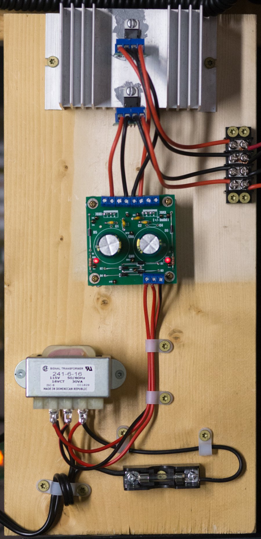
Regulators mounted to large heat sink for power dissipations above 0.5 watts
This is a positive & positive setup using two LM7805 regulators
Have a question? Ask us via email
, Previous Page . Next Page
o Ordering g Glossary s Sitemap u Updates
![]()